Vibration-Resistant Fuse Design Ensures Stable Protection on Harsh and Uneven Roads
News 2025-11-17
In modern transportation electronics, fuse performance under vibration is no longer a secondary concern. Vehicles, construction machines, agricultural equipment, and off-road platforms expose electrical systems to constant mechanical shock, wide temperature swings, and dirt intrusion. A conventional fuse, optimized only for static bench conditions, can suffer from contact fatigue, micro‑arcing, or intermittent opens when subjected to rough terrain. Vibration-resistant fuse shockproof design directly addresses this gap by reinforcing mechanical stability, preserving accurate overcurrent protection, and extending system uptime in demanding road and off-road environments.
Structural Design for Vibration Damping
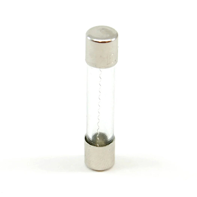
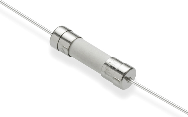
Vibration-resistant fuses begin at the mechanical level, where the internal element, terminals, and body are engineered as an integrated shock-absorbing system. Reinforced end caps, low‑mass fuse links, and mechanically locked terminations prevent fretting and movement under repeated impact. The housing often uses high-strength, temperature‑stable polymers or ceramic bodies that resist cracking and maintain dimensional stability. Some designs incorporate spring-loaded or crimped internal connections that maintain constant contact pressure despite chassis flex and shock loads. This structural approach ensures that the electrical path remains consistent, preventing nuisance openings caused by mechanical stress rather than genuine overcurrent faults.
Electrical Performance Under Harsh Vibration
Shockproof design must preserve the core function of the fuse: predictable current-time behavior. The fuse element geometry is chosen to minimize resonance and avoid fatigue fractures during sustained vibration profiles typical of commercial vehicles and off-road machinery. Contact plating and surface treatments reduce micro‑arcing and contact resistance drift, which could otherwise alter the I²t characteristics over time. Low-inductance layouts are often preferred in high-speed DC systems, such as EV battery lines, where vibration combines with high di/dt events. By maintaining stable resistance and thermal characteristics, vibration-resistant fuses keep interruption ratings, breaking capacity, and voltage withstand parameters within their specified range throughout their service life.
Key Application Scenarios on Rough Roads
The most visible use cases appear in automotive and transportation segments where rough road conditions are routine. In heavy trucks, buses, and delivery fleets, these fuses safeguard power distribution units, telematics modules, advanced driver assistance systems, and LED lighting harnesses exposed to constant chassis vibration. Off-road equipment such as excavators, mining trucks, and forestry machines relies on shockproof fuses to protect hydraulic control electronics, engine ECUs, and safety interlocks. Agricultural vehicles operate on uneven soil, creating long-duration vibration cycles that stress standard fuse constructions; vibration-resistant designs maintain continuous power to GPS guidance, seed control, and ISOBUS communication systems. Railway, defense, marine, and utility service vehicles adopt the same principles to ensure robust circuit protection under persistent vibration, shock, and contamination.
Performance Advantages and Design Integration
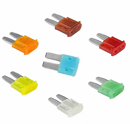
Compared with conventional fuses, vibration-resistant variants reduce nuisance trips, improve mean time between failures, and cut unplanned maintenance in fleets that operate daily on rough surfaces. Stable contact resistance helps maintain accurate sensing thresholds, which is crucial where downstream electronics expect tight protection coordination. Shockproof packages also simplify harness and PCB design by reducing the need for extra mechanical damping or isolation fixtures around the fuse holder. Many series support wide operating temperature ranges, high surge tolerance, and compatibility with automated assembly processes. PCB-mount, bolt‑down, and blade-style formats allow designers to select the form factor that best fits the current rating, available space, and serviceability requirements while preserving vibration endurance.
Selection and Implementation Considerations
Engineering teams evaluating vibration-resistant fuses should review standardized vibration and mechanical shock test reports, such as those aligned with ISO, IEC, or automotive standards. Key parameters include rated current, voltage, breaking capacity, time‑current curves, and environmental ratings including IP and temperature class. Careful matching of the fuse rating to inrush, steady-state load, and fault profiles prevents premature opening while maintaining effective short-circuit protection. Layout guidelines should minimize mechanical leverage on the fuse body, using secure housings, proper torque on bolted connections, and strain relief for nearby conductors. When implemented as part of a coordinated protection scheme, a shockproof fuse can significantly improve system reliability in rough road environments while keeping replacement and downtime costs under control.
1What makes a fuse vibration-resistant?
A vibration-resistant fuse uses reinforced mechanical construction, secure internal terminations, and stable contact materials that prevent movement, fatigue, and micro‑arcing under continuous shock and vibration.
2Where are vibration-resistant fuses most commonly applied?
They are widely used in automotive, heavy truck, off-road machinery, agricultural vehicles, rail systems, and defense or utility fleets operating on harsh and uneven surfaces.
3How should engineers select a shockproof fuse for rough roads?
Engineers should confirm vibration and shock test compliance, verify current and voltage ratings, check time‑current curves against load profiles, and ensure the chosen package can be mounted in a way that limits mechanical stress on the fuse body.