Wiring Connections in Fuse Box Assemblies That Shape Overall System Stability
News 2025-12-22
Stable wiring inside a fuse box is fundamental to electrical performance in vehicles, industrial control cabinets, and building power distribution panels. Every junction, crimp, and routing decision directly affects voltage integrity, noise immunity, and long‑term reliability. Poorly executed connections cause intermittent faults that are difficult to trace, turning a robust design into a maintenance burden. Modern applications demand that fuse box layouts sustain high current, respond predictably to faults, and remain serviceable under thermal and mechanical stress.
Connection Architecture and Current Paths
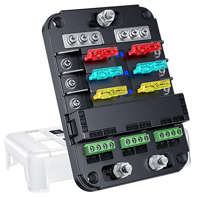
The architecture of fuse box connections determines how current flows, how faults are isolated, and how voltage drops are distributed. Busbars, terminal blocks, and blade fuse sockets must be arranged to minimize resistive losses and prevent bottlenecks in high‑load branches. In automotive systems, for example, separating power‑train, safety, and infotainment rails improves stability by reducing mutual interference. Using appropriately rated copper conductors, matched contact plating, and calibrated fuse ratings ensures that protective devices trip before traces overheat, protecting both wiring and downstream modules.
Contact Quality, Materials, and Thermal Behavior
Contact interfaces inside the fuse box are a dominant factor in long‑term stability. Poor crimping, inadequate spring force, or mismatched materials increase contact resistance, generating heat and accelerating oxidation. High‑performance systems adopt tin or silver plating, verified crimp height, and defined insertion forces to maintain low milliohm resistance over thousands of mating cycles. Thermal management is equally important: grouping high‑current fuses, providing airflow paths, and using heat‑resistant polymers prevent localized hotspots that can deform housings, loosen terminals, and trigger cascading failures across multiple circuits.
EMI Control, Layout Strategy, and Application Scenarios
In data‑rich environments such as EV platforms, telecom racks, or PLC cabinets, fuse box wiring must support both power delivery and electromagnetic compatibility. Twisted pairs for sensitive sensor lines, separation between high‑di/dt loads and low‑level signals, and star‑point grounding reduce conducted and radiated noise. Shield terminations should be routed to dedicated grounding points rather than arbitrary fuse positions. In harsh environments—off‑highway machinery, marine systems, or renewable‑energy combiner boxes—sealed housings, grommeted cable entries, and corrosion‑resistant terminals preserve performance under vibration, moisture, and salt exposure.
Serviceability, Diagnostics, and Performance Advantages
A well‑engineered fuse box simplifies diagnostics while preserving system stability. Clear labeling, color‑coded circuits, and logical segmentation by subsystem shorten troubleshooting time and reduce wiring errors during service. Incorporating test points, blown‑fuse indicators, or smart fuses with telemetry enables rapid detection of overload conditions and trend analysis of current consumption. These design choices increase uptime, reduce warranty costs, and extend the life of connected electronic modules.
1. How do wiring choices influence fuse box stability?
Optimized conductor sizing, low‑resistance contacts, and clean routing reduce heat, voltage drop, and EMI, resulting in predictable circuit protection and longer component life.
2. Which applications benefit most from robust fuse box wiring?
Automotive, EV, industrial automation, telecom infrastructure, and renewable‑energy systems gain higher availability, fewer nuisance trips, and more consistent power quality.
3. What design features improve long‑term performance?
Use of quality crimp terminals, controlled contact plating, thermal‑aware layout, EMI‑conscious routing, and accessible diagnostics all contribute to durable, stable fuse box operation.